In a previous blog “Modeling Welds for Finite Element Analysis (FEA) (add link to this blog before posting)“. We discussed methods for predicting stress around a fillet weld. In this post, we want to present a streamlined process for weld analysis using FEA (specifically ANSYS Workbench) as the primary tool. We will focus on how to properly size fillet welds, a skill which has proven particularly useful for complex weldments.
Method 1 (a more traditional approach)
Before discussing the use of FEA to size welds lets first explore the traditional approach to sizing a weld as outlined in “Determination of Weld Loads and Throat Requirements Using Finite Element Analysis with Shell Element Models — A Comparison with Classical Analysis” by M. A. Weaver.
Example using Method 1:
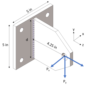
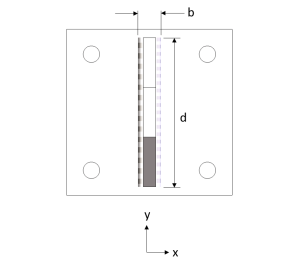
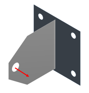
A simple T-joint made from 3/8″ thick ASTM A36 plates is to be double-sided fillet welded. The base plate is fixed at the bolt holes and a load of [-200, -2000, 3000] lbf is applied at the hole as shown below:




Shortcomings of the Method 1:
While the approach using Method 1 to calculating weld size can be an effective method, it is not always practical. Consider the following shortcomings:
- It can be somewhat time-consuming, especially in weldments more complex than the preceding example.
- It assumes that the external forces are distributed evenly across the weld. This is not the reality and can be a dangerous assumption.
- For complex weld seams and shapes, Method 1 cannot be used without simplifying the analysis.
Method 2 (Use FEA as a tool to extract more accurate weld loads)
FEA programs can be used as a more accurate way of predicting loads through a weld. By simulating the load case through FEA, we can use ANSYS to tell us what the loads and moments are in the area specific to the weld of interest.
Example using Method 2:
Consider the same loading scenario as Example 1:
- Using ANSYS Workbench, we convert the model to a shell.

- Size the Mesh. For this particular model, we want the mesh size to be a certain fraction of the weld length. Our Weld length is 4 inches so a mesh size of .1 will give 40 exact elements across the weld seam. This will be important later.

- Add a split line offset from the weld edge. This split line will define the area from which to pull forces and moments. Offsetting from the edge ensures that the nodes are inside the weld and not shared by multiple bodies.

- Before running the simulation, “Nodal Forces” must be turned on. This parameter is accessed through “Analysis Settings/Output Controls” in the sidebar (as shown):

- Before running the simulations we want to set up 3x “User-Defined” results from the ENFOZ, ENFOY, and ENMOY parameters. These parameters give the nodal resultant forces and moments in the direction of the selected axis.
- Access these user-defined results by clicking “Solutions/Worksheet” and scrolling down to the correct parameters (noted above).
- Right-click the 3 parameters and select “Create User-Defined Result”.

- The last step is to scope these User-Defined results to the path that we created. This can be done to all three User-Defined results at once by highlighting all three and changing “Scoping Method” to “Path” and selecting the predefined path (weld seam).

- Below are the results for ENFOZ which are the resultant forces at each node in the Z direction scoped across the weld seam path.
- Alternatively, the data can be viewed in the “Tabular Data” section and then copied and pasted into an Excel sheet.

Sanity-Check Calculated Values:
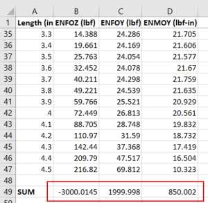
As a double check that the ANSYS values are pulling correctly, the sum of the results should MATCH the originally applied loads (Note: the sums may not match the original loads exactly due to rounding errors):
- Approximately 3000 lbf in the Z direction
- Approximately 2000 lbf in the Y direction
- 200 lbf * 4.25 in = approximately 850 lbf-in about the Y axis

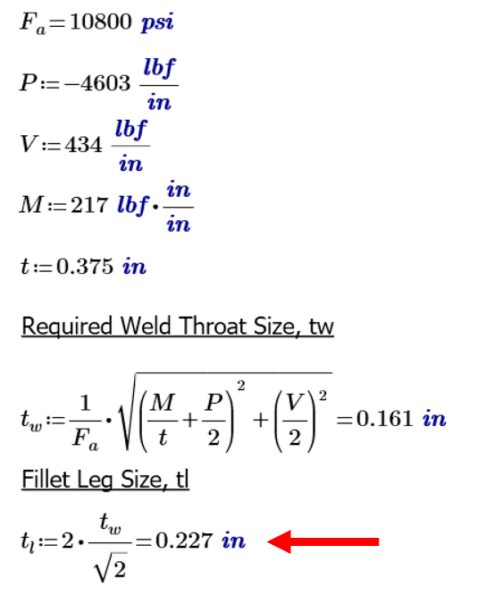
The equation suggested by Weaver to solve for weld throat size is:

Where
- M=Moment (about weld axis)
- P=Normal Load
- V=Shear Load
Note: In order to modify the format to match our excel sheet, we divide each value by the length of each element (.1 in).

Plots of the M results:
For the M-plot we see an evenly distributed moment across the weld.
Because the average and max moments are fairly close in value, we will be conservative and use the max value of 217 lbf-in/in for the calculation.


Plots of the P results:
For P we can see the value of using FEA to find distributed force through the weld.
We can see that through the length of the weld, there is a large range of pulling force. It is suggested to use the maximum absolute value of P in the calculation, -4603 lbf/in.


Plots of the V results:
For the V plot we see a less extreme distribution of force but still some resulting variation:
The analyst has the option of using the average or the max value of V in the calculation.


Here, because the force is fairly evenly distributed with the two end nodes being the exception, we will use the average value of V which equals 435 lbf/in.

Weld Size Calculation:
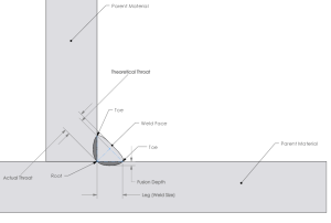
Plugging the values of P, V, and M into Weaver’s equation we can calculate a throat size of 0.161 in and a fillet leg size of 0.227 in.
This value is about 10% smaller than the traditional leg length calculation of 0.26 in and should be considered more accurate since more accurate force values were used in the calculation.
Conclusion
While the two methods shown above provided comparable results, the real value of Method 2 is when used to size welds in more complex weldments, such as weldments using multiple plates of different shapes and thicknesses. For complex weldments, Method 1 might prove very time-consuming. Utilizing FEA to identify critical weld areas and extract the associated forces and moments (Method 2), might assist in streamlining the weld-sizing process and provide more accurate results.


