Confused about welds? Are you unclear about the different elements of a weld symbol? What does it actually mean in regards to the applied weld? The following is meant to answer some questions faced by engineers when it comes to specifying welds, specifically fillet welds.
Fillet Weld Terminology
Terms:
- Parent Material – the pieces to be joined with a weld.
- Toe – the outer edge of the weld where the parent material and the weld material meet.
- Weld Face – the outer surface of the weld.
- Root – the point opposite the weld face where the weld material and the parent material meet.
- Throat – The distance between the face of the weld and the root of the weld. The theoretical throat of the weld assumes a flat weld face while the actual throat will generally be larger.
- Leg – The distance from one face of the parent material to the opposite Toe
- Fusion Depth – the distance that the weld penetrates the parent material.
Where are Fillet Welds Used?
Fillet welds are used at Tee, Lap, and Corner joints. They are also used to join pipes to plates and in conjunction with groove or bevel welds as a capping weld.

These joints result in perpendicular or near perpendicular parent material faces. Fillet welds are the most common type of weld because they are the easiest type of weld to manufacture and design. These types of joints are preferred for the same reason.
Weld Symbol Explanation?
Weld symbols are used to define where a weld is needed, it’s size and type. The American Welding Society publishes a complete definition of these symbols in AWS A2.4, Symbols for Welding, Brazing and Nondestructive Examination. Here we will only cover the basics of these symbols with regards to fillet welds.
Basic Fillet Weld
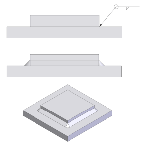
The simplest example of a fillet weld symbol is shown below. The fillet symbol BELOW the line indicates that the weld is applied to the same side of the joint. Inverting the symbol (placing it ABOVE the line) indicates that the weld is applied to the opposite side of the joint:
Same Side

Opposite Side

Fillet Joint

Lap Joint

Corner Joint
Double-Sided Fillet Weld
If both sides of the joint need to be welded the symbol should be modified. Adding the fillet symbol above the horizontal line indicates that a weld should be added to the side opposite the arrow.

Fillet Joint

Lap Joint

Corner Joint

Weld Size
The leg size is not required in the symbol but if a certain weld size is desired it should be included to the left of the fillet symbol.


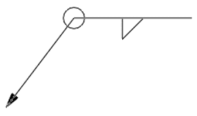
All-Around Symbol
If a weld is required around the circumference of a pipe or on every side of the connection. The “all-around” symbol should be added.

Weld Length and Spacing:
Welding the entire length of a joint can be time-consuming, expensive, and potentially cause warping. Depending on the application, intermittent or “stitch” welding can provide a viable alternative. Stitch welding is defined as several shorter length welds at a specific interval along the joint. To define a stitch weld, the length and center spacing must be designated. These parameters are placed to the right of the fillet symbol and are separated by a hyphen (length-spacing). The example below designates 2-inch-long fillet welds placed every 4 inches on center:

When stitch welding on both sides of a joint (double-sided fillet), it can be advantageous to stagger the welds. This essentially means that the welds do not directly oppose one another and the welds on one side of the joint the spaces on the other. This practice is often used for joint stability and to mitigate warping. The symbol resembles a double-sided fillet weld, but in this case, the fillet symbols are offset as shown below:


Engineering Analysis of Welded Structures
Static Loading
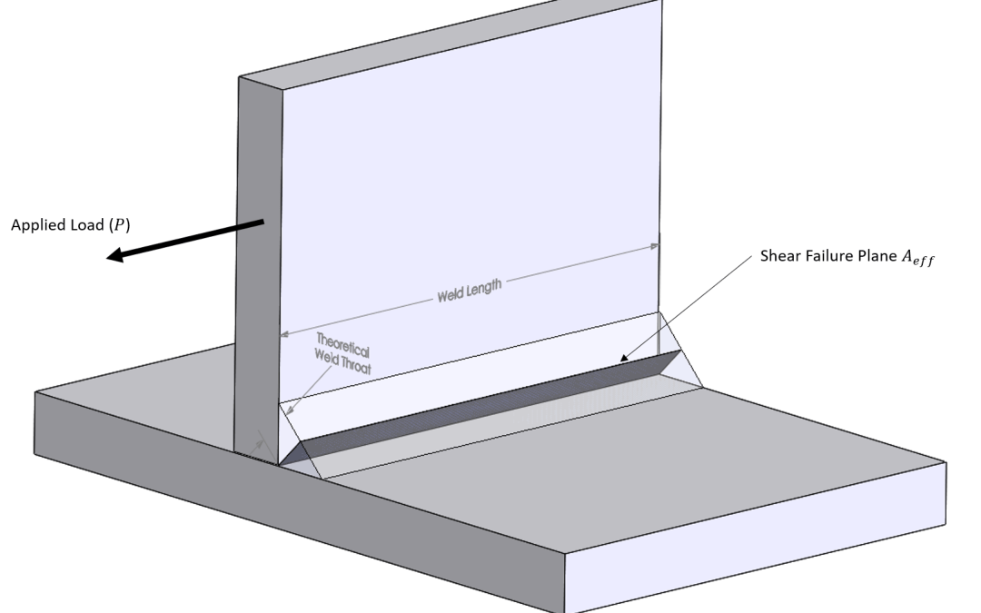
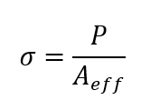
Under static loading conditions, fillet welds with no defects are likely to fail in shear along the throat of the weld. This remains true regardless of the loading type, tension, compression or torsion. The stress in the weld is determined by dividing the static load by the effective area. The effective area can be calculated by multiplying the length of the weld by the theoretical weld throat:

In typical steel welds, the weld filler material will generally have a higher yield and ultimate strength than the parent material. For this reason, only failure of the parent material is considered. Keep in mind that the above applies ONLY to static loading conditions!
Fatigue Loading
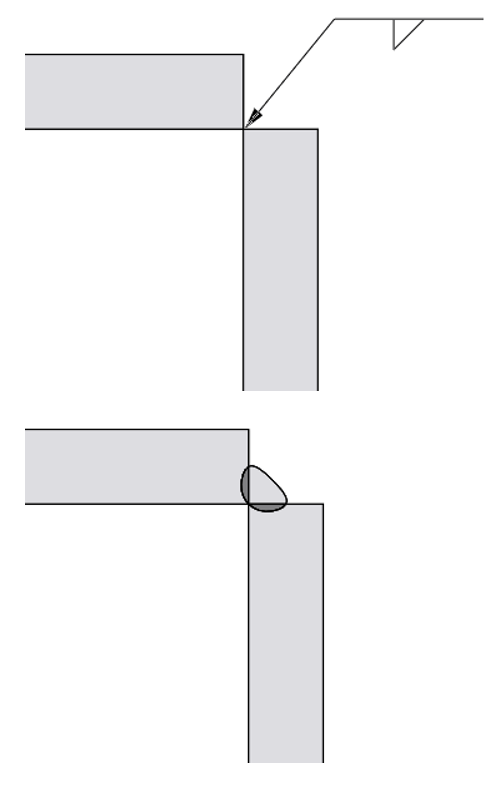
In fatigue situations where a cyclical or periodic load is applied, (e.g. roller coaster vehicle, motor frame, bridge with traffic, or any welded structure/component where loading is variable), welds are analyzed using significantly lower allowed stresses than used in a static analysis. In fatigue, failure cracking typically begins at the toe or the root of the weld. Failure initiates at the weld toe because of stress concentrating features created as a byproduct of the welding process. Failure occurs at the root of a weld joint due to the presence of a “crack” created by the un-fused portion of the weld joint. Fillet welds generally do not completely penetrate the welded joint:

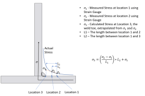
Hot-Spot Approach
Determining the stress at the weld toe is made difficult by the lack of toe uniformity. This makes the effect of specific stress concentrations hard to define. One approach, known as the Hot-Spot method, utilizes stress evaluated at two points close to the welded area. Stress at the weld toe is then extrapolated from those calculations/measurements. In Finite Element Analysis Finite Element Analysis (FEA) weld geometry is generally not included. Instead, calculated stresses in the analysis where the weld toe will occur, based on specified weld size, are considered peak and those that are within the welded area are discounted as unrealistic.

Stresses at the root of the weld are difficult to define by inspection. Use of the Hot-Spot Method (defined above) assumes that the stresses at the root of the weld are lower than those at the toe. However, where high fatigue loads exist complete joint penetrating welds (CJP) are a good idea. This will eliminate the “crack” at the interface between the 2 bonded members, eliminating the root as a possible failure initiation point. CJP welds have higher strength allowance but tend to be more expensive requiring special non-destructive testing and inspection.
Stress life curves for welded members can be found in AISC 360-16 Specification for Structural Steel Buildings Figure C-A-3.1 Fatigue resistance curves.
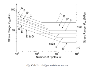
An explanation of the stress categories can be found in AISC 360-16 Table A-3.1 A summary of this table with respect to welded joints is shown below. In addition to the threshold Stress Range for infinite life a fatigue coefficient is also given that can be used to determine fatigue life if the stress is above the fatigue limit using this equation.

Terms:
- ηSR – the number of loading cycles to failure
- Cf – fatigue constant
- Δσ – the difference between maximum periodic loading and minimum periodic loading
