
Have you ever tried to create a new component to augment or replace an existing component only to spend hours fighting the interface (i.e. bolt hole placement, flange profiles, etc.)? Have you ever tried to model an existing component in a CAD system such as SolidWorks only to be frustrated when unable to obtain an accurate measurement of a critical feature? Enter the 3D scanner.
3D scanning at its core is the process of digitizing a real-world object for use in a virtual environment. There are various technologies capable of accomplishing this, but the specific technology highlighted in this post is Structured-Light scanning using an Artec Eva scanner.
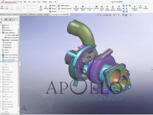
Garret T25 Turbocharger:
In a recent project, we had the opportunity to scan and create a SolidWorks model of a Garret T25 Turbocharger. This particular turbo was used on a few sports cars of the early 90’s, namely the Mitsubishi Eclipse and Eagle Talon. It has since become a popular choice within the car modification community due to its high reliability and the relative availability of used, low-cost units.

Our task was to scan the outer surfaces of the turbo and produce an accurate 3D representation of the interface points. The interface points include connections to intake air, pressurized air, exhaust, oil, and coolant. While the associated flanges and bosses themselves can be measured manually without much difficulty, the relationship to one another cannot. The model is intended to be used in SolidWorks to enable an engineer or designer to iterate on exhaust component designs to obtain optimized airflow and efficiency values within the engine compartment space limitations. The scan may also be used to create a more accurate flow simulation model for use in CFD analysis or cooling simulations. The ultimate use of this scan is to facilitate the creation of a vehicle specific parts kit. Having a complete virtual model will ensure fit and help to smooth the transition from prototype to production.
So, how do we get from physical object to 3D model?
Prepare and scan the subject. A well lit, indoor workspace works best. The Artec Eva has a relatively large field of view so it is a best practice to have space to walk around the object. This will allow the scanner to be used in the best position relative to the subject. A clean planer surface supporting the object helps to facilitate post-scan processing.


Process raw data. Using Artec Studio 12 allows the base to be removed, multiple scans to be aligned, and holes in the mesh to be filled to produce a seamless surface.
Combine scans. Fusion of the mesh produces the final geometry that can be converted into other data formats for further processing in CAD programs or used for 3d printing.

Convert to SolidWorks. Processing using Geomagic for SolidWorks results in a workable solid by defining regions which are used to extract surfaces and critical dimensions. Once all geometry is converted from the Artec scan data into SolidWorks features, the scan data is removed leaving behind a fully representative solid part.
Finish model with interface flanges. Using the new solid part as a reference, the interface components can be easily created in SolidWorks to match.


Hide Scan, begin design. With the relationships between all connection points established, the design process can begin. The scan is hidden in order to improve SolidWorks performance.
3D scanning allows our team to interface with the real world in a way difficult to achieve with any other method. The effect is more accurate designs, fewer fit-up issues, and decreased turn-around time, all of which improve our bottom line.